Why Keep a 1–2 mm Gap Between Rod and Stack Plate on a Self-Stacking Belt?
A self-stacking belt can meet every dimension on the drawing and still lie badly if one small clearance is missing: the space between the rod end and the stack plate.

Short answer
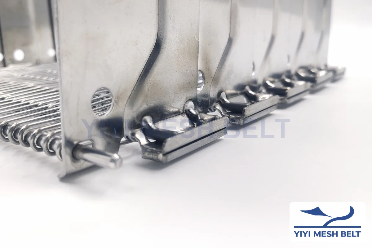
On our standard self-stacking belt, the rod end stops 1–2 mm short of the top of the stack plate. The rod must not be pushed up against the plate: the gap lets the belt release its tension across the width, so the centre of the belt does not arch up. The gap is set on the approved drawing and checked on the trial section and in final inspection.
I am Sunny Ye, Global Sales Director at YIYI MESH BELT in Ningjin, Shandong, China. The rod-to-stack-plate gap is one of the smallest numbers on a self-stacking belt drawing, and one of the first things we write on every production order. Here is why.
At a glance
| Product | Self-Stacking Belt in SUS304 or SUS316 |
|---|---|
| Rod-to-stack-plate gap (standard) | 1–2 mm (0.04–0.08 in) |
| Heavy duty and reinforced heavy duty | Confirmed on the approved drawing |
| Why it matters | Lets the belt release its tension across the width, so the belt centre does not arch up |
| Where it is fixed | Approved drawing and production order |
| Where it is checked | Trial section and final inspection before packing |
What is the rod-to-stack-plate gap?
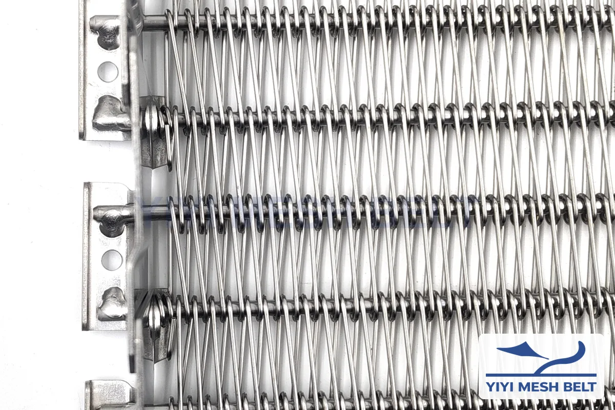
Every rod on a self-stacking belt ends at the edge, inside a side link and a stack plate.
The rod-to-stack-plate gap is the clearance between the end of the rod and the top of the stack plate it passes through. On our standard construction it is 1–2 mm. The rod is located in the link, but it is not pressed against the top of the plate.
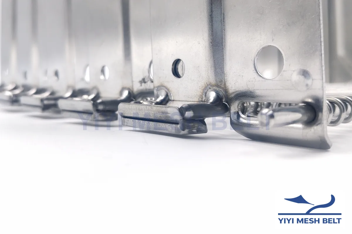
A self-stacking belt collapses on one or both sides on the inside of the turn, and the links on the collapsing side have long slots. On one recent 420 mm order with 5 mm rods, the slot was 5.5 mm wide. The long-slot side carries a small washer, and the wire ends on the short-slot side are finished as the drawing or the customer's sample shows. The gap sits on top of all this: whatever the slot, the rod end must not touch the top of the stack plate.
| Part | What it does | Typical value (standard) |
|---|---|---|
| Rod | Carries the mesh across the belt width | 5 mm diameter, 30 mm rod pitch |
| Side link with long slot | Lets the edge collapse on the inside of the turn | Slot width to the approved drawing |
| Stack plate (side guard) | Carries the tier above | 1.5 mm thick; 60 / 80 / 90 / 100 / 120 mm high |
| Washer | Fitted on the long-slot side | To the approved drawing |
| Rod-to-stack-plate gap | Leaves room for the belt to release its tension | 1–2 mm |
Why 1–2 mm and not zero?
Zero looks tidier. It is not better.
If the rod is pushed up against the stack plate, the belt cannot release its tension across the width, and the centre of the belt can arch up instead of lying flat. A 1–2 mm gap leaves just enough room for the belt to settle. That is why our production orders say, in so many words, that the rod must not reach the top of the link plate.
Older descriptions of this belt as having "no gap" are no longer used in our product data. A belt where every rod is tight against the plate may look solid on the bench, but under tension that tightness has nowhere to go.
The gap is also small on purpose. It is a clearance, not looseness. The rod is still located in the link and welded at the edge, and the tier still has to engage cleanly with the tier above.
Where is the gap set and checked?
A clearance this small has to be written down, or it disappears.
The 1–2 mm gap is shown on the approved drawing and written on the production order. We check it on the trial section together with the other dimensions, and again in final inspection before the belt is packed.
| Stage | What happens to the gap |
|---|---|
| Drawing approval | The 1–2 mm gap (or the value for a heavy-duty belt) is shown on the drawing you approve |
| Production order | The gap and its purpose are written for the workshop |
| Trial section | Checked with the dimensions, the stack plate angle and the layer engagement |
| Mass production | Rods assembled and welded without pushing them up against the plate |
| Final inspection | Gap checked again with geometry, welding and dimensions before packing |
Every self-stacking belt order is also tested on a drum before shipment. You can see the production and inspection steps in our Self-Stacking Belt production and quality control document.
How does welding affect the gap?
The gap is set at assembly. Welding can spoil it.
Our production orders ask for a low welding current at the edge, so the stack plate is not burned through, and for welding in sequence from one end of the belt to the other instead of jumping around. Both keep the rod ends where assembly put them.
A burned-through plate is the obvious failure. The quieter one is heat pulling the edge out of line. Welding steadily in one direction keeps the edge even along the length, so the gap stays the same from the first rod to the last.
Is the gap the same on heavy-duty belts?
Not automatically.
The 1–2 mm value is for our standard construction with 5 mm rods. On heavy-duty belts with 6 or 7 mm rods, and on reinforced heavy-duty belts with 4 × 15 mm reinforcement pieces, the gap is confirmed on the approved drawing.
The reinforcement piece sits between the link and the mesh, so the edge is built differently. We do not copy the standard value across. For how the constructions differ, see standard or heavy-duty self-stacking belt.
What should you send so we can confirm it?
For a new belt, the drawing is enough. For a belt made to sample, we need to see the edge.
Send the equipment drawing or the belt drawing, or a sample section of your current belt with close-up photos of the rod ends, side links and stack plates. Tell us the rod diameter, the side guard height and which side of the belt collapses.
| Information | Why we need it |
|---|---|
| Drawing or sample section | Shows the rod end, link and stack plate as built |
| Close-up photos of the edge | Rod ends, slots, washers and wire end finish |
| Rod diameter (mm / in) | 5 mm standard; 6 or 7 mm heavy duty |
| Side guard height (mm / in) | Confirms the stack plate |
| Collapsible side and rotation direction | Confirms which links carry the long slots |
Our spiral and self-stacking inquiry checklist lists everything else for a quote.
When this is not the right choice
This article is about the self-stacking belt. A drum-driven Spiral Freezer Belt has no stack plates, so this clearance does not apply there. And if your equipment drawing or your original belt shows a different rod-to-plate relationship, we do not simply apply 1–2 mm: we review it with engineering before we quote, and the approved drawing decides.
From our engineering experience
A rod pressed against the plate is easy to miss in a photo of the mesh, so when a buyer sends photos of an old belt, I always ask for close-ups of the edge as well: rod ends, slots and stack plates.
My advice: ask for the gap on the drawing, in millimetres, and check it on the trial section before you approve the full length.
Evidence from our work
| Situation | A 420 mm SUS304 self-stacking belt with 90 mm side guards, collapsible on one side, made to the customer's sample |
|---|---|
| What we checked | The production order required a 1–2 mm gap so the rod did not reach the top of the link plate, a 5.5 mm long slot for the 5 mm rods, a washer on the long-slot side and low welding current at the edge |
| Why it matters | With the gap written on the order, the 2 m test order and the 100 m order that followed were built to the same edge |
| Result | 2 m test order in 2025, followed by a 100 m order in 2026 to the same data |
| Buyer lesson | Put the gap on the drawing, then the reorder inherits it |
| Situation | A 420 mm SUS304 self-stacking belt, 173 m, with 60 mm side guards |
|---|---|
| What we checked | 1–2 mm rod-to-stack-plate gap, no burning through the stack plate, trial production photographed for the customer's confirmation before batch production |
| Buyer lesson | Ask for trial-section photos that show the edge, not only the mesh |
For the full production sequence, see how a self-stacking belt is made on yiyimeshbelt.com.
FAQ
What is the rod-to-stack-plate gap on a self-stacking belt?
It is the clearance between the end of a rod and the top of the stack plate (side link) it passes through. On our standard self-stacking belt it is 1–2 mm, set on the approved drawing.
Why should the rod not touch the top of the stack plate?
If the rod is pushed up against the stack plate, the belt cannot release its tension across the width and the centre of the belt can arch up. The 1–2 mm gap leaves room for the belt to settle flat.
Is the gap the same on heavy-duty belts?
The 1–2 mm value applies to our standard construction. For heavy-duty and reinforced heavy-duty belts, the gap is confirmed on the approved drawing.
How do you control the gap in production?
The gap is written on the drawing and the production order, checked on the trial section with the other dimensions, and checked again in final inspection before packing. Welding current is kept low so the stack plate is not burned through.
Can you build a belt with no gap?
We do not offer a no-gap design as a standard. If your equipment drawing or original belt shows a different rod-to-plate relationship, we review it with engineering before we quote.
Conclusion
The rod end stops 1–2 mm short of the top of the stack plate, so the belt can release its tension and lie flat. Put the gap on the drawing, check it on the trial section, and the full belt and every reorder will follow it.
Useful files for your project
I work on metal conveyor belt projects, from new spiral freezers to belt replacement. I share project notes and replacement checklists on LinkedIn.
Technical reviewer: Sunny Ye, Global Sales Director, YIYI MESH BELT · Last updated: 2026-10-27
© 2026 Ningjin Yiyi Mesh Belt Co., Ltd. All rights reserved. Photos, drawings and data on this page belong to YIYI Mesh Belt and may not be copied or reused without written permission.